The project of the displacement tourist boat «Crab»
Unhurried and reliable motor boats, sewn by local craftsmen from boards, are well known to every resident of the north-west of our country. Thudding with the exhaust of the most diverse and sometimes exotic engines, they carry their unhurried service on rivers, lakes, in countless lips and bays of the northern seas.
The prototype of these vessels were fishing and household boats of the distant past — carbases, finks, gdovki, etc. Motors replaced the oars and sails, but the design of the boat hulls has hardly changed. As two hundred years ago, they are made of planks, cutting out frames from beams or bending them from the stems of young freshly cut fir trees.
Such vessels also find their fans among the townspeople who, for the best rest, honor to measure a thousand kilometers along the rivers of their native land, and on Sundays — to walk to places rarely visited by land tourists — islands, inaccessible along the shore of remote bays. A crudely crafted «with a margin for durability» case usually does not cause much concern to its owner; a simple engine reliably and with minimal fuel costs delivers its owner where it needs to be. The only thing required from the owner boats, it's no rush.
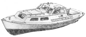 It is for those who find the greatest pleasure from a long stay on the water, and drawings of a displacement tourist boat «Crab» are offered. Any master boatman can help build this boat by applying the usual method of construction and the available material. It is important to maintain the contours of the hull, which are close to optimal for speeds from 8 to 12 km / h; accordingly, it makes no sense to put engines more powerful than 20 hp, which will bring the Crab boat to the most unfavorable mode in terms of water resistance and fuel consumption — relative speed Fr=0.5-0.6. The lower power limit can be determined at 3-4.5 hp, when there is a risk of poor handling and loss of boat speed when strong wind. In such cases, a good propeller thrust is important, which can be obtained at a low rotational speed (1000-1500 rpm) and a large diameter.
| Basic data of the boat «Crab» | |
|---|---|
| Longest length, m | 6,51 |
| KVL length, m | 6,02 |
| Maximum width, m | 2,00 |
| Width by KVL, m | 1,80 |
| Minimum side height, m | 0,79 |
| Draft by KVL, m | 0,45 |
| Displacement by KVL, t | 1,00 |
| Passenger capacity, people. | 6 |
| Recommended engine power, kW/hp | 4,5-15/6-20 |
| Speed, km/h | 10-12 |
Be that as it may, on such boats, water tourists from Arkhangelsk, Vologda, Leningrad and other regions made a lot of fascinating trips, during which they did not care about fuel, engine repairs or weather conditions.
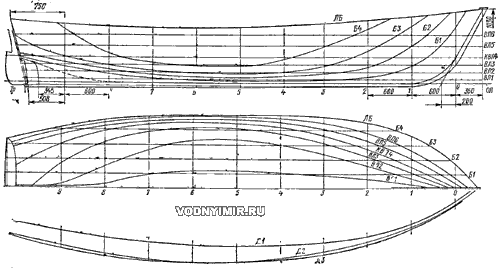
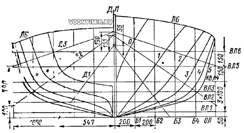
Considering the recommended engine power, the boat is designed with a low side by modern standards and a small cabin. To reduce the wave resistance, a relatively narrow body (L/B=3.3) with a high coefficient of longitudinal completeness φ=6.65 was chosen (see the ordinate table).
Ordinates of the theoretical drawing of the boat «Crab», mm
(on the outer skin).
| Lines of the theoretical drawing | Frame numbers | |||||
| 0 | 1 | 2 | 3 | 4 | 5 | |
| Half-latitude from DP | ||||||
| Side line — LB | 335 | 710 | 889 | 968 | 995 | 1000 |
| Waterline — VL6 | 139 | 506 | 745 | 876 | 948 | 973 |
| VL5 | 70 | 400 | 639 | 798 | 895 | 945 |
| KVL4 | 20 | 286 | 525 | 711 | 828 | 886 |
| VL3 | — | 209 | 430 | 621 | 747 | 823 |
| VL2 | — | 135 | 309 | 454 | 585 | 663 |
| VL1 | — | 53 | 124 | 182 | 213 | 242 |
| Heights from OL | ||||||
| Side line — LB | 970 | 910 | 855 | 810 | 778 | 755 |
| Batox — B4 | — | — | 725 | 506 | 310 | 225 |
| B3 | — | 775 | 459 | 229 | 157 | 130 |
| B2 | — | 500 | 220 | 128 | 96 | 80 |
| B1 | 761 | 236 | 86 | 55 | 43 | 39 |
| Diagonals from DP | ||||||
| Diagonal — D3 | 219 | 547 | 751 | 875 | 958 | 993 |
| D2 | 200 | 505 | 700 | 850 | 940 | 1000 |
| D1 | 169 | 463 | 635 | 716 | 755 | 772 |
| Theoretical drawing lines | Frame numbers | |||||
| 6 | 7 | 8 | 9 | Tr | ||
| Half-latitude from DP | ||||||
| Side line — LB | 996 | 975 | 930 | 829 | 653 | |
| Waterline — VL6 | 979 | 958 | 899 | 744 | 605 | |
| VL5 | 941 | 917 | 848 | 728 | 544 | |
| KVL4 | 900 | 869 | 773 | 598 | 283 | |
| VL3 | 839 | 770 | 619 | 325 | — | |
| VL2 | 652 | 530 | 300 | 20 | — | |
| VL1 | 250 | 196 | 56 | 25 | — | |
| Heights from OL | ||||||
| Side line — LB | 745 | 745 | 760 | 790 | 840 | |
| Batox — B4 | 225 | 270 | 390 | 692 | — | |
| B3 | 134 | 172 | 242 | 352 | 652 | |
| B2 | 82 | 110 | 181 | 271 | 379 | |
| B1 | 39 | 51 | 121 | 215 | 338 | |
| Diagonals from DP | ||||||
| Diagonal — D3 | 998 | 975 | 912 | 804 | 634 | |
| D2 | 1000 | 961 | 885 | 767 | 621 | |
| D1 | 769 | 735 | 662 | 570 | 451 | |
Theoretical drawing of the boat «Crab»
The control post is located in the wheelhouse open from the stern, which has a small height of about 1.6 m. So if the driver opens the hatch provided above his place in the roof of the cabin, he can control the boat while standing on a low banquette. It is not necessary to increase the height of the cabin because of the influence of wind on the speed and controllability of the vessel.
General view of the boat
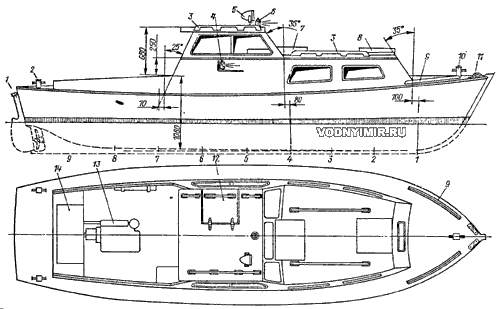
1 — hinged steering wheel; 2 — aft mooring bollard; 3 — handrail; 4 — side distinctive light; 5 — headlight; 6 — top light; 7 — sliding hatch cover; 8 — forelock; 9 — foot rails; 10 — biteng; 11 — kip plank; 12 — hatch above the driver; 13 — engine; 14 — stern locker.
Here, in a well-ventilated and relatively free place, a galley with a gas tank and a sink for washing dishes is provided. When the galley is not needed, it can be closed with a lid and turned into a seat for two people. When food is being prepared, the crew of the boat can sit on folding chairs and a stern locker. The cockpit, which has a length of more than 2 m together with the wheelhouse, is spacious enough for all 6 people to find a place here. It is better to go on a long hike with a smaller crew — no more than four people. There is not much room in the cabin of the «Crab», so two people will have to sleep on air mattresses in the cockpit. The cabin can be equipped with a wardrobe for shore clothes, a small locker-bar, bunks with small lockers and a shelf in the forepeak.
General location of the boat
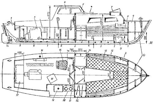
1 — afterpick; 2 — engine; 3 — fuel tank; 4 — wheelhouse; 5 — sliding hatch; 6 — hatch cover cover; 7 — forelock; 8 — shelf for small items; 9 — forepick; 10 — shelf; 11 — outrigger bucket; 12 — internal stitching of the sides with slats; 13 — sofa-bed; 14 — cabinet-bureau; 15 — driver's seat; 16 — fuel tank; 17 — locker cover-seats; 18 — folding chair (raznozhka); 19 — sink; 20 — gas taganok; 21 — folding double-leaf door; 22 — wardrobe.
The general layout drawing shows an 8-horsepower air-cooled UD2-M1 engine paired with a reverse gearbox from the SM-557L engine. It is better to install such engines openly, and if you close the hood, then it is necessary to ensure the inflow of air to cool the cylinder block and its ejection (of sufficient cross-section, otherwise the engine will overheat). In wet, cold weather, it is good to direct a jet of hot air to the wheelhouse and cabin with the help of a screen; wet clothes hung near the engine dries quickly. Due to the absence of a water cooling system, UD engines are easier to maintain. Let's add another important factor — they are economical. With the specified «UD2-M1», for example, and a 1:1.64 gearbox, the «Crab» can reach a speed of 12 km/h, consuming about 0.28 liters/km of fuel.
The hull of the boat, as already noted, can be built in various ways, focusing on the construction of boats of local types. The drawing of the structure shows laminated frames, pre-glued according to templates from the rails. The casing of the hull can be carried out directly on these frames installed on the slipway as patterns. It is also possible to use natural frames, the components of which, as on many boats of local types, are cut out of boards and connected to each other on plates of the same thickness. If oak or ash is used for the manufacture of frames, the blanks are made 22-24 mm thick; if pine is used, then 28-30 mm thick. When marking on the board, the parts must be positioned in such a way that the overgrowth of the wood fibers is minimal, otherwise the frames may get cracks (especially in emergency circumstances, for example, when stranded in a wave). In the best designs, the natural frames are made three-layered, replacing the linings with strips of water-resistant plywood 4-6 mm thick glued on both sides of the frame. The spacer — the distance between the frames — is adopted the same as on many folk boats — 600 mm.
Housing with rack-and-pinion sheathing. The body is sheathed with slats 20 mm thick and 40-60 mm wide, attaching each rail to the previously installed rail with nails 3x60 (80 mm) in increments of 100-120 mm, and then to the frames with screws 4X45 mm (see Fig. bookmark and cross sections on frames, 187 KB). The slats need to be cut from dry pine boards (cedar, larch is suitable) with a thickness of 25 mm, taking into account the margin for their stretching (3-4 mm) and for the final stripping of the skin. They begin to sheathe the body from the tongue-and-groove belt adjacent to the keel. It is better to prepare it from a 150 mm wide board. Due to the fact that this board can be narrowed to the stem, subsequent slats will no longer need to be reduced in width in the nose.
Housing with edge-to-edge sheathing. In this method, the sheathing boards are connected to each other — riveted along the edges, so the hull has sufficient rigidity without setting additional frames (in addition to the general location of the boat shown in Fig.). This requires pine or spruce boards with a thickness of 20 mm (in pure form). The width of the board in the middle part of the body length should be 120-150 mm.
To the frames, keel and stem, the skin is fixed with 5x45 screws, and the edges are riveted with nails-rivets (preferably copper) with a diameter of 3.5-4 mm. Under the nails, it is necessary to pre-drill holes of a slightly smaller diameter; after setting, the inner ends of the nails need to be riveted on washers.
The body with a plank covering is smooth. With this method of sheathing, adjacent belts have no connection with each other, except through the frames. With a shpation of 600 mm and a skin thickness of 20 mm, it is not necessary to worry especially about the strength of the case, but the appearance of leaks in the grooves is not excluded, even with the densest caulking. In the design of some folk boats with such a skin, additional elements are used — triangular slats-fins, which are fixed with frequent metal brackets in the grooves of the skin cut from the outside. It is best to put one bent frame between the natural frames indicated in the drawings, or generally all the frames are bent. The spatula in this case will be 300 mm, the thickness of the skin can be reduced to 15-17 mm.
The blanks of bent frames are cut out of oak, ash (section 16x30 mm) or spruce (section 18x35 mm) rails, steamed and put into the housing, after all the sheathing is assembled on temporarily installed patterns or natural main frames. With the variant with bent frames, the body weight will be less.
Let us now briefly dwell on the manufacture of some of the most important parts of the case.
The keel can be made using any of the methods shown in the figure. The keel consists of a beam placed on an edge, or the keel itself, with a thickness of 40 mm and a rubber band — a board attached to its upper edge, bent into a layer, or two slats on the sides. The choice depends on the capabilities of the builder, but the construction with slats requires a tight fit and more fasteners to prevent possible leakage through the grooves between the keel and the slats (this option is good when using waterproof glue).
Options for assembling the keel: a — with a resenkil from a board; b — with side rails
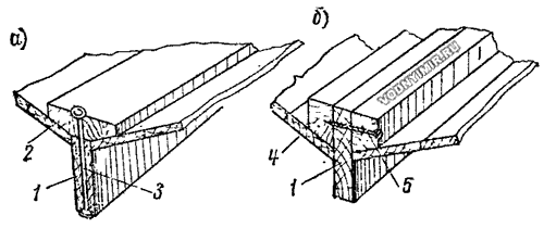
1 — keel; 2 — rezenkil; 3 — bolt M6, step 200-250: 4 — rail 40x30; 5 — screw 5x80, step 120.
The structural drawing shows the height of the keel (together with the resenkil) on each frame. The rezenkil has a constant width of 120 mm and narrows only at the junction with the stem (up to 70 mm). In the stern from the 7th frame, the rezenkil must be planed to a thickness of 23 mm.
The stem (see fig. bookmark and cross sections on frames, 187 KB) are assembled from three parts. For their manufacture, it is necessary to first draw the full-size outline of the stem according to the theoretical drawing and transfer the dimensions of all its parts to the plaza, guided by the design sketch. According to the received marking, the parts are pre-processed, after which they are tightly fitted one to the other. The most difficult thing is to choose a tongue-and-groove, i.e. to make a recess for the sheathing boards in the lower part of the stem; this work needs to be done completely already on the slipway.
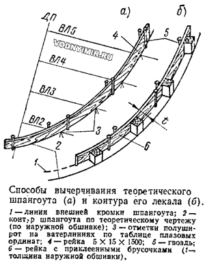 To mark the frame frames, it is necessary to draw a full-size plasma drawing and put the thickness of the outer skin inside the outline. This can be done with a compass or a flexible rail with sticks glued on one side of it.
Linings, floras and beam knits are riveted with copper nails-rivets with a diameter of 4-5 mm with a washer gasket under the riveted end (galvanized steel bolts can also be used). It is necessary to put so many rivets on the joints so that each part is fastened with at least three rivets. The toptimbers of each frame must be connected with a temporary crossbar — a shergen-bar at a height of 800 mm from the OL.
The transom lining, which is recommended to be made in the tongue, is assembled simultaneously with the strapping directly on the plaza.
It is more convenient to assemble the hull in the keel down position by first installing a bookmark on the slipway according to the theoretical drawing: a keel with a resinkil, a stem and a transom.
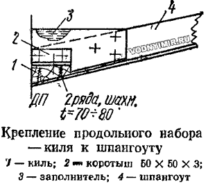 After checking their position, the frame frames are attached to the rezenkil using short steel corners or by passing two bolts M6 vertically through the flora. It is desirable to put squares in the joints of the privalny beam with frames.
The ends of the idle beams are cut into the halt beam. Beams on the 1st, 2nd, 3rd frames are placed when assembling the frame frames.
The deckhouse is mounted after installing the deck deck, assembled from 15 mm thick boards for caulking, installation of karlengs 8 (see Fig. bookmark and cross sections on the frames, 187 KB) and mounting the bulkhead on the 5th frame. In the nose, the «decorator» of the cabin is a nasal inclined coaming, which must be assembled from 17 mm boards or plywood 8-12 mm thick. It is advisable to install another time frame at the 4th frame to give the side coaming a bend. The beams of the cabin are marked out in the same way as the beams of the hull and cut the ends into the shelf (into the «swallow tail»). The roof of the cabin can be sheathed with plywood 6 mm thick, clapboard or slats 12 mm thick. In any case, it is desirable to cover the roof and deck with canvas (on liquid putty), securing it with beads and collars.
Boat projects for self-construction
Share this page in the social. networks or bookmark:

