Gliding amphibian «Triton» — project and construction of an amphibious boat
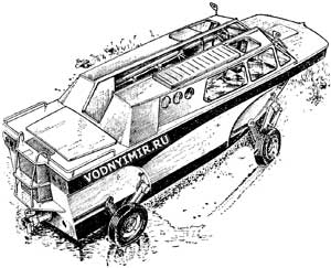 General considerations. The creators of most of the amphibians known to us followed one of two main directions. The first is the creation of a floating car, which necessarily has limited seaworthiness, the speed on the water is low and it is not adapted for any long trips on water routes. The second is the construction of boats that can drive on the highway; in the appearance and design of these machines, the features of ordinary motor vessels clearly prevail, but their ability to move long and fast on land is most often limited.
Reaching a compromise, i.e. creating a full-fledged amphibian, is not an easy engineering task. Nevertheless, when designing the «Triton», from the very beginning we set ourselves exactly such a task — to achieve the operational equivalence of the amphibian when using it both on water and on land. We proceeded from the fact that in terms of comfort in long-distance navigation, our new amphibian should not be inferior to the usual a cabin boat of a 5-meter class and at the same time have significantly more autonomy than a car, on the way of which there are usually campsites, shops and gas stations. This consideration was due not only to the capacity of fuel tanks three to four times larger than that of a car, but also to the possibility of equipment on board comfortable sleeping places, the creation of necessary conditions for cooking, storing some stock of food, etc.
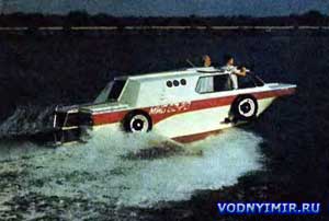 Wheels are up. «Triton» is planing. |
It was clear from the very beginning that with all options for solving «land» problems, the planing contours of the amphibian, which guarantee full speed, should remain intact. Preliminary calculations have shown that, both for hydrodynamic reasons and for habitability conditions, the overall dimensions of the amphibian hull (body) cannot be smaller than the «minimum motor-powered boat» type that has developed in the boat building, i.e. about 5 m long and 2 m wide. At the same time, it turned out that the dry weight of an amphibian could not be less than the dry weight of a passenger car, the units of which are supposed to be used, and at the same time it would be more than the weight of a cabin boat of comparable dimensions by at least 300 kg; in both cases, about 1000 kg came out. Thus, with a full displacement of 1300-1400 kg, it was possible to use the «GAZ-21» engine on an amphibian with a power limit of up to 80% of the nominal, the resulting specific load of 22-23 kg/hp did not exceed the limit value limiting the possibility of running on the planing mode.
Both to ensure the amphibian's high cross-country ability when moving on water, and according to the layout conditions, we considered a water cannon to be the only possible type of propulsion.
As a result, the design type of our amphibian was determined as follows: a four-wheeled planing water-jet amphibian-a limousine with suspensions outside the dimensions of the hull along the cheekbone; when swimming, the suspensions should rise completely above the water, and if necessary, be completely removed.
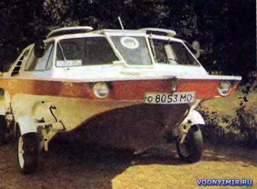
| Technical data of amphibian «Triton» | |
|---|---|
| Dimensions (in parentheses — overall), m: | |
| length | 5,11(5,45) |
| width | 1,94(2,25) |
| height wheelhouse | 1,48(1,70) |
| Base/track, m | 2,35/2,06 |
| Ground clearance, mm | 220 |
| Turning radius, m | 7 |
| Overhang angles front/rear, deg. | 28/18 |
| Gross weight (displacement), kg | 1400 |
| Mass distribution on the axis — front/rear, % | 45/55 |
| «GAZ-21» («Volga») engine rated/permissible on water, hp | 75/60 |
| Maximum speed, km/h: | |
| on the highway at a mass of 1400 kg | 90 |
| on the water at full water displacement. | 42 |
| water removing suspensions | 45 |
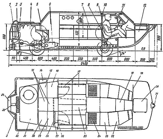 General location and longitudinal section of the amphibious boat «Triton»: 1 — water cooling radiator; 2 — oil radiator; 3 — deck duct; 4 — engine; 5 — gearbox; 6 — gearbox; 7 — removable part of the seat back when installing a side berth; 8 — folding TV table; 9 — ceiling lamp; 10 — pillars; 11 — electric motor and wiper drive; 12 — gas tank; 13 — steps of the rear internal trapezoid; 14 — window of the on-board duct; 15 — shelf for laundry; 16 — wardrobe; 17 — double seat across the body; 18 — step of the front internal trapezoid; 19 — forepeak bulkhead; 20 — cover of the nozzle; 21 — ring-duck; 22 — seat; 23 — spacer (support of the front seat in the lower position); 24 — front seat after layout; 25 — contour of the table in the unfolded form; 26 — galley door; 27 — table panels folded and pushed into the galley niche; 28 — telescopic table guide; 29 — galley; 30 — galley shelves; 31 — engine compartment cover; 32 — railing; 33 — cover over the neck of the water radiator; 34 — ladder. |
Design features and layout of the housing. The hull is made completely closed — without a cockpit and side potopchin — narrow sections of the deck along the sides. A through passage along the amphibian — along the DP line (the roof above it can be opened) connects the fore and aft sections of the deck. The central wing of the windscreen reclines to the right side; the rear door and roof panels above the aisle are folded into a compact package and fixed on the right side of the cabin roof.
The rejection of on-board potopchins, which made it possible to make a cabin from side to side, significantly increased the useful volume of the cabin, and the central passage improved the conditions of habitability: you can move in full height on the amphibian, there is no danger of slipping off the inclined potopchins into the water. The cabin is quite spacious: its length is 3.55 m; the area utilization rate is 68%.
To improve visibility in difficult sailing conditions, two hatches with reclining covers are arranged above the front seats — the driver's and navigator's seats.
The sharp-cheeked contours of the hull have a moderate keel (5° on the transom); the sides are given a small collapse (they are vertical in the places where the suspensions are installed). The bow branches of the frames have a very large camber, which made it possible to obtain a spacious, almost rectangular bow deck. The horizontal bend of the cheekbone is formed by the edge of the side skin released below the bottom, followed by filling the «corner» with epoxy putty with fine sawdust. Note that in the given theoretical drawing (and in the table of plaz ordinates), the zygomatic splash guards, vertical sections of the sides in the area of the suspensions and the edge of the bow frames are not shown for simplification. The slope of the transom is consistent with the angle of installation of the water cannon and is equal to 6° to the vertical.
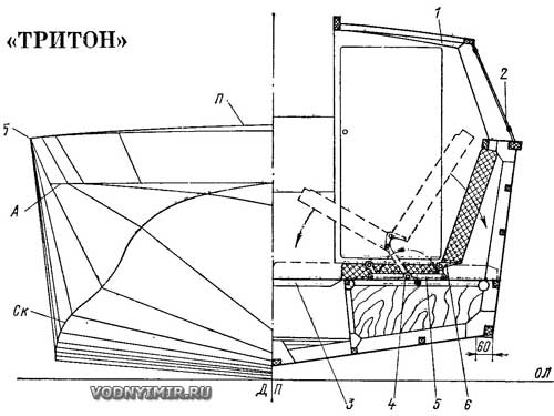 Theoretical body and structural section along the midsection: 1 — cabin roof; 2 — glass seal, rubber profile; 3 — removable flooring; 4-6 — lever device for sofa layout |
Table of plaz ordinates of the gliding amphibian «Triton»
| Line | frame number | |||||||||
| 1 | 2 | 3 | 4 | 5 | 6 | 7 | 8 | 9 | 10 | |
| Height from the main, mm | ||||||||||
| Keel | 700 | 210 | 110 | 80 | 60 | 46 | 33 | 24 | 10 | 0 |
| Skula — SK* | 740 | 610 | 360 | 250 | 185 | 144 | 125 | 110 | 90 | 74 |
| Bort — B | 950 | 950 | 950 | 950 | 950 | 950 | 950 | 950 | 950 | 950 |
| Deck — P in DL | 985 | 1000 | — | — | — | — | — | — | 995 | 980 |
| A | 770 | 770 | 770 | — | — | — | — | — | ||
| Half-width, mm | ||||||||||
| Bort — B | 850 | 900 | 930 | 950 | 950 | 950 | 950 | 950 | 950 | 950 |
| Skula — SK* | 250 | 520 | 650 | 770 | 830 | 845 | 845 | 845 | 845 | 845 |
| A | 740 | 810 | 883 | — | — | — | — | — | — | — |
| * The points of junction of the side and bottom branches of the frames are given. | ||||||||||
Headlights, front lights and distinctive lights are «sunk» in niches along the edges of the deck outriggers and are well protected by canopies — overhanging sections of the bow deck. A rigid ladder is mounted on the transom, it is convenient for operation both on water and on land and at the same time serves as a fence for radiators, a muffler and a reversible steering complex of a water cannon.
The housing set is made according to the longitudinal-transverse system using oak and pine. The skin is made combined: the aviafanera of various thicknesses (from 2 to 7 mm) is pasted with fiberglass on an epoxy binder (up to seven layers were laid on especially loaded areas.)
Structurally, the body (body) of the amphibian is load-bearing. More precisely, a type of load-bearing body is used — a «load-bearing bottom» with high box-section beams and local reinforcements. Being a part of the whole, such a structure is a solid sectional-closed platform consisting of compartments-shpation, tightly closed by the flooring of the inner bottom.
The frames are assembled on the knits on both sides. The toptimbers have a variable cross-section with a broadening to the cheekbone. The beams of the longitudinal set and the sheets of the skin and bulkheads were joined «on the mustache». All connections are made on epoxy glue with pressing screws or clamps. Only galvanized or cadmium fasteners were used. All wooden surfaces of the case are coated with epoxy varnish.
Unsinkability is ensured by sealing the forepeak and sections of the «bearing bottom».
Since we had to hang a lot of «unnecessary» parts and assemblies on the hull of an ordinary boat, the problem of weight reduction was particularly acute. At all stages of the work, both the choice of materials used and the dimensions and cross-sections of the bearing parts were carefully justified. An important reserve for weight reduction was the multipurpose use of structural elements, which, of course, is possible only if they are rationally disposed. For example, vertical stringer spars, which are part of the «load-bearing bottom» system, also serve as walls of lockers; they, being reinforced in the aft part, form the basis of the submotor foundation. The size of the spacer is made variable (400, 450, 550, 600 mm) and is not only strictly linked to the layout of the interior space, but excludes any duplication of the transverse set, and is consistent with the installation dimensions of the chassis units. Two pairs of reinforced frames were introduced into the mounting system of the suspension support units. Located at the structural intersections of the main connections of the sides and the bottom, these support units acquired rigidity with an increased coefficient of deformation strength, which made it possible to reduce the cross sections and the mass of local reinforcements on the hull. Two pillars on the sides of the passage partially unload the cabin roof set (this, by the way, was done with a long-range sight: it should help in the future to equip the amphibian with auxiliary sailing armament-a sloop with a top-end staysail).
Cabin equipment. The internal space of the amphibian is conditionally divided into three parts: the central one is the salon; the «utility block» located aft of it, including a galley and a wardrobe, and the «wheelhouse», the conditional boundary of which is the backs of the front seats, raising the floor level and pillars.
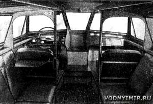 Interior of an amphibious boat cabin. |
The seats in the cabin are located on the lockers with their backs along the sides; four of the six seats can be easily transformed into a full-size double seat located across the amphibian hull. To reduce weight, all seats are made of PVC-1 foam plates with a thickness of 50 mm, covered with foam and sheathed with leatherette. The horizontal panels of the seats are connected to the backs pivotally.
The front seats have a non-collapsible duralumin frame. They can be installed in two positions at a height with a difference of 400 mm. The lower position is the usual «car»; the upper position is used only on the water, with the hatch covers open, giving a complete «illusion» of an open boat. The sun visors, tilted to the upper position, well protect the driver's face from the oncoming wind, i.e. they play the role of a windscreen.
There are 12 lockers and an extensive trunk in the forepeak (above the gas tank) for storing equipment and food supplies; in addition, onboard pockets and a navigator's «bag» are equipped for storing route maps, binoculars, photo-cinema equipment and small things.
Interior ventilation is natural, through partially open or fully open hatches, doors and roof panels over the aisle in any combination.
A few words about our mini-galley located on the starboard side (for more information, see this page). In fact, it does not seem to be in the cabin, since being closed and with a table pushed into a niche, it repeats the size and decorative design of the wardrobe located on the opposite side. But when opened, it is very convenient. It has enough space for two «bumblebees» and all kinds of kitchen utensils; there is a pull-out sink with a tap connected to it from a tank with drinking water; a thermos, small dishes, tea, coffee, sugar are stored on the shelves of a volumetric door in niches.
A pull-out folding table (size 480x1230 mm) freely accommodates four people. Spread out only half, it plays the role of a kitchen table.
The galley is illuminated by the reverse side of the salon lampshade (through the hole in the fence on which it is installed). Here, in the cabin, a folding auxiliary table is mounted on the back of the driver's seat; we put a TV on it.
Chassis, steering, brake system. Independent single-lever suspensions of the «G» type are used. The levers are facing backwards; they have a welded structure, and even during manufacture they have the installation angles of the pivot, the camber of the front wheels and the convergence angle of the rear wheels. The angle of convergence of the front wheels is regulated by a transverse thrust inside the housing. The levers of the rear suspensions are made of pipes welded in pairs in a vertical plane, inside which, as in a sealed crankcase, the drive chains on the wheels work.
Springs and hydraulic shock absorbers are chosen the same for both pairs of suspensions (from «ZAZ-968»), but due to the difference in the axle load on the front levers, they are installed in front of the wheel axles, on the rear — behind (this balances their work). The axes of the levers of all suspensions are hollow, with a large internal diameter: in the front, this is done for the free movement of the lateral steering rods, in the rear, for the placement of cardan joints, sprockets, bearings and their eccentric housings, with which the chains are tensioned.
When installed on the housing, the suspension axles are inserted into the support sockets with nylon bushings pressed into them and are kept from axial movement by bayonet-type grippers. Due to the large areas of friction, the wear coefficient of the parts is negligible.
The upper supports for springs and shock absorbers are special «traps» into which the «shoes» of the springs are pushed and latched with pins along the guides.
When moving through the water, the suspensions together with the wheels rise up along the sides. It is enough to press the spring-loaded pin so that the «shoe» is released from the «trap», and the suspension has the freedom to move up until the latch clicks. All operations to lift the four suspensions take a few minutes.
Tires 6,15x13" are applied.
Steering is based on the parts and steering mechanism of «ZAZ» cars with significant additions due to the use of a fundamentally different scheme. When developing a new scheme , two conditions were set:
1) when lifting and dismantling suspensions, all operations should be minimized;
2) when returning the suspensions to the working position, it is necessary to exclude additional adjustment of the wheel mounting angles. This was fully possible thanks to the solution, the essence of which is to combine the longitudinal axis of the side rods with the swing axis of the suspension levers and the transfer of forces to the rotary fists through rocker levers.
The shaft of the steering mechanism is equipped with a disconnecting device with a cam clutch that closes either the drum of the cable drive on the flaps of the water cannon, or the steering mechanism on the wheels.
The brake pad system «ZAZ» is used in full: the foot hydraulic drive is made for all wheels, and the manual cable (parking) — only for the rear.
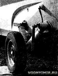 Amphibious front suspension. |
In order to simplify the installation of suspensions on the body and their dismantling, four dry connectors are installed on the outboard sections of the hydraulic line, eliminating the possibility of leakage of brake fluid and the need for subsequent pumping of the entire system. Each connector consists of two hemispheres, the bases of which are covered with elastic membranes. The hemispheres that end the pipelines of the internal highway are fixed on the sides; the reciprocal «consumable» hemispheres installed at the ends of the pipelines of the wheels are pressed to the side with cap nuts. When the brake pedal is pressed, both membranes deform, squeezing the brake fluid from the «consumable» hemispheres into the working cylinders of the wheels — braking occurs. The volume of the «consumable» hemispheres is 2.5 times larger than the volume used in the working cylinders during braking and, therefore, there is a possibility of compensation in case of a breach of the tightness of the external, outboard main. In the absence of brake fluid in any hemisphere (or even in all four), the brake system does not fail: under the influence of pressure in the trunk, when the pedal is pressed, the membranes break through, and the brake fluid, flowing freely from the inner to the outer trunk, performs its work as in a conventional hydraulic system.
When traveling on water for a long time, the suspension with wheels can be removed. This possibility has been achieved at the cost of some design complications («shoes», «traps», dry hydraulic brake connectors, etc.), but if you leave the wheels on the shore, the payload increases by 160 kg. To remove the suspensions, it is enough to unscrew the four cap nuts on the hydraulic brake connectors; disconnect the side rods from the pendulum levers and unscrew the outer ends of the handbrake cables.
Amphibious power plant. The «GAZ-21» engine, as well as a homemade gearbox and gearbox with a differential from the «ZAZ» car, represent a single power unit mounted close to the transom, above the water cannon, on five rubber pads. With this arrangement, the drive to the wheels is carried out in the shortest way and the length of the engine compartment is extremely reduced.
The intake pipe of exhaust gases before exiting through the transom is equipped with a compensating spacer — bellows that absorb engine vibration. The silencer is rigidly fixed under the bottom step of the ladder.
Access to the crankshaft ratchet is carried out through a hole in the transom, blocked by a spring-loaded lid with a seal. If necessary, you can use the wind-up handle from the passenger compartment; for this, a ratchet is installed on the intermediate shaft of the gearbox.
The aft location of the engine required a number of additions to the standard cooling system. To increase the intensity of the water radiator blowing, a guide casing is installed on it; instead of the standard four-bladed, a light six-bladed fan with blades deployed in the opposite direction is made, which is brought to the transom through the extension of the water pump shaft; an oil radiator from «GAZ-51» is added to the oil system. Both radiators and the fan are isolated from the engine compartment. Fresh air comes to them through a separate deck duct and partially through a wide gap between the transom and the casing of the water radiator.
On water, when the water cannon is running, an external cooling circuit is automatically connected to a water heat exchanger embedded in the standard line between the radiator and the water pump. Seawater also begins to flow into the oil cooling coil in the engine crankcase and into the gearbox jacket; some of the water is discharged through the exhaust system.
The water temperature in the cooling system at all modes of movement on land and water is stable at 85 °C, the oil temperature does not exceed 90 °C.
The exhaust manifold is enclosed in a lightweight casing. Both on water and on land there is a centrifugal electric fan, the inclusion of which is interlocked with the gas pedal. Before starting the engine, even before the ignition and starter are turned on, when the pedal is pressed two or three times, the engine compartment is well ventilated. When the engine warms up, when the ignition system is still running (up to 1000 rpm), the fan turns off. At medium speeds, low speed is turned on and at high speeds (above 2500 rpm) — high.
 Air enters the engine compartment through air intakes built on both sides of the cabin; along the guides it is fed to the gearbox and the engine and discharged through special holes in the transom.
For power take-off on the water cannon, gearbox and winch (not yet delivered), a gear reducer with a neutral was used. The gear ratio of the gearbox is 19:18; gears are straight-toothed, the module is 3 mm; heat treatment is 48-52 HRC. Compared with the slant-toothed gears, the noise of such gears is only not much more (by 8-10 dB), but their use has allowed to reduce the dimensions, and most importantly — the weight of the gearbox.
The gearbox housing is welded. All holes and seats were processed on a boring machine. A water cooling jacket is welded onto the side walls and bottom of the gearbox. The gearbox is attached to the crankcase of the regular «GAZ-21» clutch on four regular studs, to the flange of the box — on eight studs with a paronite gasket seal. The control of the gearbox «vodomet» — «neutral» — «wheels» is displayed on the sector located to the right of the driver, next to the gearshift lever.
An intermediate unit, the pantograph, is included in the transmission control line with the «ZAZ» differential; this was required due to the fact that the control shaft and the rod of the box slider are at different height levels.
The design described in «Boats and yachts» No. 11 and 25 was adopted as the basis of the water jet propulsion, but some additions and changes were made. All parts are made of stainless steel; the inlet of the water pipe is expanded; an inspection hatch is installed; thrust and radial bearings with oil seals are mounted on a deadwood, which is reinforced on the body of the water pipe with additional knits-kerchiefs; the protective grille is installed obliquely with an angle of about 14° to the keel line; the fairing of the straightening apparatus is elongated and in this removable part of the fairing (threaded connection) there are a bearing and an oil seal of the rear shaft support; the sections of the rotor blades and the straightening apparatus are halved; the gap between the shell and the rotor blades is 0.4 mm; the reverse steering complex is significantly facilitated.
The conduit is welded from two symmetrical halves; their gouging became possible thanks to longitudinal incisions on the cylindrical part of the workpieces — two for each half. Both halves, fitted butt-to-butt and previously tightened on the block with wire bandages, were boiled in one go. This option, in our opinion, gives the least distortion of the geometry of the conduit and extremely reduces the length of the welds.
The electrical equipment is standard automotive, but the light alarm is made according to two schemes with a switch to «water» and «earth». The headlights are also left in the «boat» scheme «water» so that they can be used, for example, when approaching the shore in the dark; the front turn indicators are duplicated as signal lights. The circuits are equipped with a «mass» switch.
Regular indicators of the engine operating mode are supplemented with an electronic tachometer and a lag. It is also possible to control the oil temperature in the engine, for this purpose the TM-101 sensor installed in the oil tank can be connected to the water temperature indicator from time to time via a two-position toggle switch on the dashboard.
The parking brake handle (also known as the reverse of the water cannon) and the buttons for manual control of the gas and air damper are displayed on the dashboard.
All communications for remote control of the engine, gearbox, gearbox, reverse of the water cannon, as well as the parking brake and speedometer cables pass under the slates of the cabin, and the cables of the water cannon handlebars running along the left side at the level of the seat backs are passed through a vinyl tube, which protects against accidental contact with grease.
Sea trials and operation of the «Triton» for two seasons have confirmed our calculations and demonstrated the operability and reliability of all units and systems.
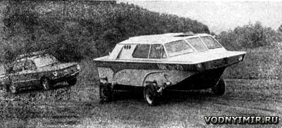 When driving on land, the «Triton» behaves on an equal footing with the car even on a dirt road. |
A maximum speed of up to 100 km/h was shown on the highway; handling is good, the course is very soft. However, we consider it advisable to limit the operational speed to about 80 km/h. This is due to the fact that the gear ratio of the main gear «ZAZ» is much larger than the «Volga» (5.12 vs. 4.55); in combination with a reduction gearbox, this requires the use of excessively high, unprofitable engine speeds at speeds of more than 80 km/h.
The maximum speed on water with a low load was not measured, presumably, it will be at least 48-50 km/h.
As it is already clear from the above data, our amphibian does not fit into the standards of «Technical requirements for passenger cars manufactured individually» (from 30.VI.1980), and its appearance does not correspond to the usual automotive canons. But the «Triton» is not a passenger car, but an amphibian. And, if the general direction of our reasoning is true, then we believe that any high-speed gliding amphibian with basic automotive units cannot meet these requirements without losing its advantages.
Constructors planing amphibians with any options for implementing their ideas will always have to reckon with the patterns known in the boat building that contradict the mentioned «Technical requirements for passenger cars».
In particular, it can be argued that:
1. The rated power of the engine per 1 ton of full displacement of the gliding amphibian must be at least 60 hp, whereas the «Technical requirements for passenger cars» limit the power to 45 hp.
2. The dimensions of the hull must correspond to the displacement, i.e. they will be clearly larger than those regulated by the «Technical requirements» of 4.2x1.65 m.
It should be added to this that the appearance of a gliding amphibian, in our opinion, cannot and should not fully meet the criteria of automotive design; in contrast, a car can be floating without changing its appearance at all.
The above evidences are still waiting to be reflected in the «Technical Requirements»; their corresponding adjustment would be for amateur amphibian designers an official recognition of their right to technical creativity in this most interesting area.
Boat projects for self-construction
Share this page in the social. networks or bookmark:
